Note: This page is a work in progress.
Use N.I.N.A.'s aberration inspector (or similar software), take a photo, and measure the back focus and tilt. The goal is to achieve zero or near zero tilt and back focus error.
- If you get a positive (+) number, correct it by applying a negative (-) correction.
- If you get a negative (-) number, correct it by applying a positive (+) correction.
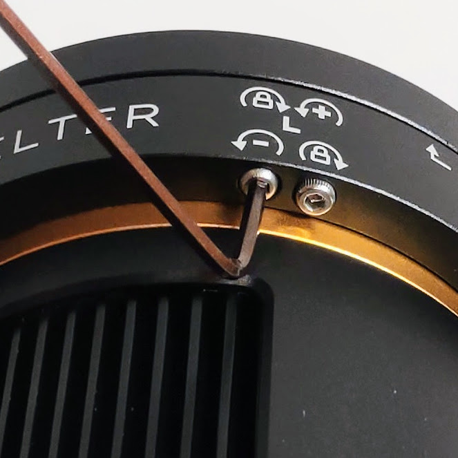
If you're wondering how you apply positive or negative corrections, wonder no more! The markings near each pair of screws will guide you. Follow these markings from left to right or from right to left, always starting with the sign (+ or -) and finishing with the lock. How much do you rotate the screws? Approximately one degree per micrometer of correction following this process:
- Identify on the surface of the O'Tilter the side or corner that you want to correct (L = Top Left, R = Top Right, B = Bottom)
- Identify the type of correction that you want to apply (+ or -).
- To apply a correction, use one of the 3 pairs of pull/push screws.
- Always start applying the correction on the screw that is marked with the sign (+ or -) that corresponds to the type of correction that you want to apply.
- Always finish by locking using the screw marked with the lock sign.
Let's use an example:
I have identified 90 micrometers of positive error in the Top Left corner of the sensor.
- I'll correct this error by using the pair of screws marked with the letter L (i.e. Top Left).
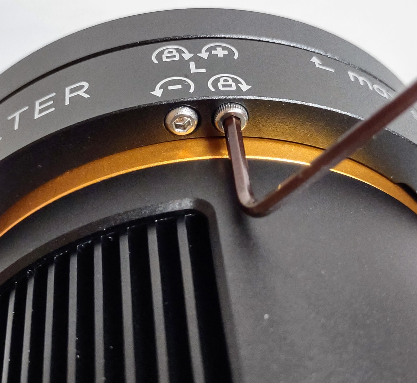
First, I'll rotate the screw marked with the negative (-) sign 90 degrees in the direction of the circular arrow.
Then, I'll rotate the screw marked with the lock sign in the direction of the circular arrow until it is firm (i.e. locks).
That's it! Take another photo and correct it again until you get the smallest possible number. If you have to apply a positive correction, then start with the screw that has the positive sign (+) and finish by locking.
Tip
The threads of the screws are very thin. If you apply too much pressure, you will break them. Also, it is always preferable to insert the short side of the Allen wrench into the screws that have a (+ or -) sign and insert the longer side of the wrench into the screws that do the locking. This way you will be able to estimate the degrees of movement using the longer side of the Allen wrench as a dial while using the shorter side of the wrench to apply a smaller torque to the locking.
FAQ
What is the back focus of the camera once the O'Tilter has been installed?
The back focus should stay very close to 17.5 mm. Make sure that you use the guitar picks as shown in the installation video of the O'Tilter to create an initial gap of approximately 0.7 to 0.9 mm between the ring of the O'Tilter and the front plate.
What is the thread pitch of the tilting screws?
The thread pitch of the tilting screws is 0.45 mm. Considering how far the screws are from the sensor and based on trigonometry, you will get approximately 1µm of displacement per degree of rotation.
Comments
Would you like to suggest corrections for or improvements to this page? Click here and tell us!